02. Clock - Eight-Bit Computer
The clock is an essential part of any computer system. It enables each instruction to be executed in sequential order. However, the clock is an external part of the computer system. This is because a clock is basically a periodic pulse generated at fixed intervals. The rising or falling edge is used to trigger a new state or instruction of the computer. Thus, generating a clock signal requires analogue components and can't be done using an FPGA.

A clock pulse
However, there are certain functions Ben Eater incorporates into his clock modules. This is the option to choose between the astable clock pulse and manual clock pulse and the capability of the computer to halt itself. Obviously, an astable clock is important for the operation of the computer as discussed before. However, Ben Eater also discusses how having a manual clock pulse which you can click through can help with debugging the circuitry. On top of this, once the computer completes all the set of instructions, it must have the ability to prevent itself from executing further instructions.
For this, Ben Eater proposes a simple logic circuit. This circuit is
able to handle all three of these functions. This circuit can be
implemented on an FPGA. This module will need four inputs and will give
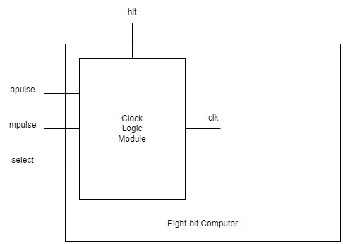
out one output. The four inputs are the apulse or the astable pulse, the mpulse or the manual pulse, select or the selection signal and hlt or halt signal. The output is clk or the clock pulse that the computer can use.

Clock module design
This can be implemented quite easily with a single line.
module clock (apulse, select, mpulse, hlt, clk);

    input apulse, select, mpulse, hlt;
    output clk;

    assign clk = ((apulse && select) || (mpulse && ~select)) && ~hlt;

endmodule
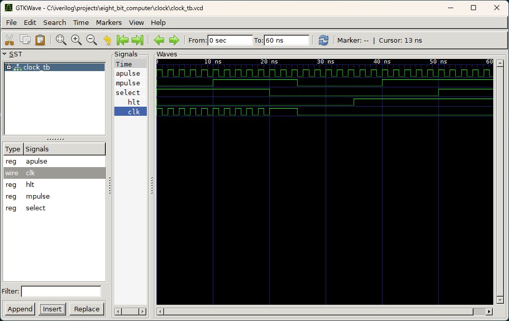
In order to test this, the test bench would need to always send a clock signal to the apulse input. We will first set the select signal low. This selects the astable clock pulse as output. So sending a high signal through mpulse won't do anything. However, if we set the halt signal to high, no matter what we do to the other three inputs, the output clock will always output a low signal.

Output waveform of the testbench
With this we have the clock logic implemented within the computer.

Structure of the computer
External Links:
- Base video: Clock logic - 8-bit computer clock - part 4
- Github Repo: Eight-Bit Computer using FPGA


Comments
Post a Comment